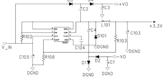
The 48V automotive system is an important development direction in the development of automotive electronics at present. There is great difference between the 48V voltage and the previous 12V automotive system. The resistor is used as the common electronic component in the daily automobile electronics. It plays a all-important role in the design of 48V automotive electronic system, and the use of resistors in DC-DC battery power supply is very important.

This problem, coupled with the emergence of electric vehicles and self-driving systems, poses a challenge to the power transmission specification, and the automotive industry will then turn to 48V battery power as a solution. Compared with 12V electrical system, 48V electrical system can reduce the distribution loss and improve the overall efficiency when the power demand is very high. All these are closely related to the resistors in the DC-DC power supply.
In a 48V system, the challenge of a resistor application in a DC-to-DC converter is that it is necessary to maintain a conversion efficiency, a size, and a low EMI similar to that of a 12V system, which makes it more difficult to meet these specifications. The benefits resulting from the use of a 48 V battery power supply should not be lost during the DC/ DC conversion process and can operate at a 2 MHz frequency to avoid interfering with the monolithic switching regulator of the AM frequency band, which is well suited for 48V automotive electrical systems.

The monolithic device uses MOSFET driver design, can produce fast, clean switch edge. This enables high efficiency, even in high-frequency operations. In addition, innovative drives minimize overshoot and suppress ringing, which will be a source of EMI generation when other drives are introduced. The integrated compensation circuit and bypass capacitor minimize the overall solution size and simplify the low EMI layout.
When the output is less than 3.1 V, the BIAS pin should be connected to an external power supply higher than 3.1 V to improve efficiency. If there are no resistors applied to this kind power supply circuit, it will not available. Then BIAS pin should be connected to the GND. In many cases, a 1MHz1.8V/8A solution works properly in 65V input transients, with the exception of low EMI, high efficiency at high frequency and a wide input voltage range. The characteristics of the circuit also include ultra-low static current and low-voltage difference.


